RUNDA TECHNICAL GUIDE
What Is Linear Actuator Stroke Length? How to Measure It
Linear actuator stroke length is the distance the output rod travels between its specified retracted and extended operating positions. It tells you how far the rod moves—not the overall length of the actuator.
For a conventional rod actuator with aligned pin-mounted ends:
Stroke length = extended pin-to-pin length − retracted pin-to-pin length.
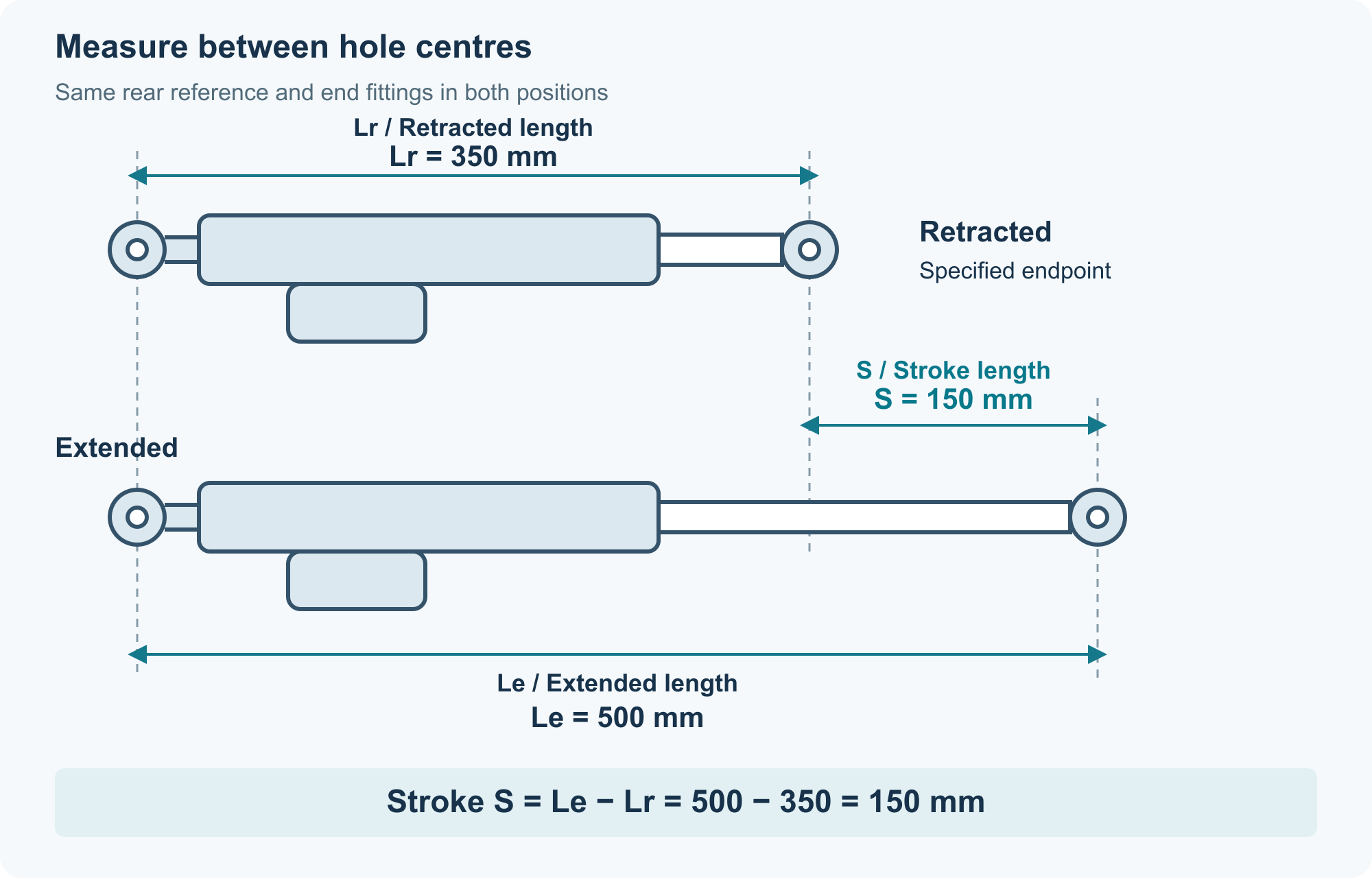
For example, 500 mm extended minus 350 mm retracted gives a 150 mm stroke. Use the mounting references on the manufacturer’s drawing: this subtraction represents axial stroke only when the specified mounting length changes one-for-one with rod travel.
To choose an actuator that fits, check three things together: its stroke, its retracted mounting length and the movement your equipment actually needs. The examples below use illustrative dimensions, not RUNDA product specifications or customer test results.
1. Stroke length vs. retracted length vs. overall length
| Dimension | What it means | What it helps you check |
|---|---|---|
| Retracted pin-to-pin length, Lr | Distance between the specified mounting-hole centres at the retracted operating endpoint | Whether the actuator fits at its shortest position |
| Extended pin-to-pin length, Le | Distance between the same centres at the extended operating endpoint | Whether it reaches the required position |
| Stroke length | Axial output-rod travel; for the aligned arrangement above, Le − Lr | How much movement is available |
| Overall length | The actuator’s complete physical length at a stated position | Space needed beyond the mounting points |
The housing or fittings may extend beyond the hole centres. A pin-to-pin measurement therefore does not describe the complete installation envelope.
When requesting a quotation, write “retracted pin-to-pin length: 350 mm,” not simply “actuator length: 350 mm.” Record Lr, Le and stroke together, using the same end fittings and measurement references.
See where to measure
Follow the centre of the rod-end hole from the retracted to the extended position. In this aligned arrangement, the rear mounting reference stays the same and the front centre moves by the stroke S. Measure centre to centre, not from the outer edge of a fitting or the end of the housing.
The 350 / 500 / 150 mm values illustrate the calculation; this is not a RUNDA model drawing. The formula assumes specified operating endpoints and a mounting length that changes one-for-one with rod travel.
2. How to measure linear actuator stroke
Before you start: identify which travel you are measuring
Full actuator stroke is the travel between its specified operating endpoints. Application travel is the mounting-distance change needed for your equipment’s intended movement. These are equal only if the application uses the full stroke.
For a loose actuator, full-travel verification should follow the manufacturer’s procedure using a suitable controlled fixture and a qualified technician. On installed equipment, measure only within its approved movement range. Those readings describe application travel unless the actuator endpoints are independently confirmed.
Do not bypass limits or force equipment past its permitted positions. Support moving loads independently before disconnecting an actuator, keep clear of pinch points, and stop and isolate power before taking measurements. Never remove an actuator that is still supporting a bed section or platform.
Step 1: Find the correct measurement points
For a conventional aligned pin-mounted actuator, identify the rear and rod-end mounting-hole centres on its drawing. Use those same references for both readings.
Threaded or offset attachments may use different references. Do not assume an arbitrary hole-to-hole measurement changes by exactly the same amount as axial rod travel.
Step 2: Measure the retracted mounting length
In a controlled full-travel check, reach the specified retracted operating endpoint according to the manufacturer’s procedure. Stop, isolate power and measure Lr.
On installed equipment, use its approved short-distance position instead and label the reading as an application dimension. A fault-stopped actuator is not necessarily fully retracted; do not force it against a mechanical stop.
Step 3: Measure the extended mounting length
For the controlled check, establish the specified extended endpoint, then stop and isolate power before measuring Le between the same references.
On installed equipment, use only its approved long-distance position. Do not treat an equipment endpoint as an actuator endpoint without confirmation.
Step 4: Subtract and label the result
| Illustrative reading | Value |
|---|---|
| Retracted pin-to-pin length | 350 mm |
| Extended pin-to-pin length | 500 mm |
| Difference | 150 mm |
This difference verifies full travel only when the readings correspond to the specified actuator endpoints and the drawing’s mounting length changes one-for-one with rod travel. Otherwise, label it as the measured working interval, not the full stroke.
Use matching units; 1 inch equals 25.4 mm. Record the measurement conditions and active travel limits.
Nominal stroke and measured travel are not identical concepts
Nominal stroke is the specified value, subject to the manufacturer’s stated tolerance. Measured travel is the result observed on a sample under recorded conditions. A small difference does not automatically indicate a defect: compare it with the specification, tolerance and measurement method for that configuration.
If the old actuator cannot move, provide its model label, drawing and installation photographs. One intermediate-position length cannot establish its full stroke.
Linear actuator dimensions: what to check before ordering
A useful dimension record lets the supplier check both reach and physical fit. Start with the mounting references in the model drawing, then add the dimensions around them. The drawing and configuration code should identify the same unit as the quotation.
| Record | How to check it | What the result tells you |
|---|---|---|
| Retracted and extended mounting lengths | Record both centre distances using the same fittings and references. Compare them with the smallest and largest distances needed across the equipment movement. | A correct stroke alone does not prove that both required positions can be reached. Use the replacement example below to compare the intervals. |
| Mounting holes, pins and fitting width | Record front and rear hole diameters, pin sizes, fitting width and orientation. Compare the dimensioned end fitting with the actual bracket, including the room needed to pivot. | A pin that enters the hole does not establish correct clearance, retention or articulation. Ask for the specified fit and tolerances rather than choosing a universal clearance. |
| Overall length, housing height and width | Mark the actuator position for each dimension and check the motor and gearbox envelope against the frame throughout the movement. Include nearby fasteners and covers. | An actuator may fit when retracted but collide as the bed backrest or platform moves. A static length measurement cannot establish full-motion clearance. |
| Cable exit and connector space | Photograph the exit direction and route. Check the cable and connector at both ends of the movement and at any tighter intermediate position. | Allow room to route and connect the cable without trapping or tension. Obtain the cable-specific bend requirements; do not invent a fixed allowance. |
| Document revision and tolerances | Send the marked drawing, model/configuration code and measured values together. Identify measurements that are unknown or taken at an intermediate position. | The supplier can distinguish an actual mismatch from a different configuration or measurement reference before recommending a replacement. |
For a bed-backrest replacement, a useful request is: “Our mounting centres must cover 350–500 mm. Please check the proposed retracted/extended lengths, end fittings, housing and cable clearance against the attached bracket drawing.” These distances are illustrative, not a recommended bed specification. Confirm force, speed and controls separately before ordering.
3. How much stroke does your equipment need?
For directly aligned sliding motion, actuator travel may equal the load’s travel. For a hinged or linked mechanism, measure or calculate the distance between the proposed mounting points throughout the required movement.
An adjustable bed backrest illustrates the difference. Its top edge rises as the backrest rotates around a hinge, while the actuator changes the distance between its two mounting pins. A 150 mm rise at the backrest edge does not establish a 150 mm actuator stroke requirement.
Start with the equipment’s required positions. Record the mounting-point distance at each, then check intermediate positions for minimum and maximum distance, clearance, alignment and force. Some mechanisms reach their shortest or longest mounting distance between the equipment endpoints.
If mounting points are not yet built, supply a dimensioned mechanism drawing or CAD motion study. Do not convert an entire rotating movement into actuator stroke using only its initial installation angle.
4. Why the same stroke does not guarantee a replacement will fit
Suppose existing mounting points must move between 350 mm and 500 mm apart. The required interval is 150 mm, but these hypothetical candidates behave differently:
| Candidate | Retracted length | Full stroke | Extended length | Result with unchanged mounting points |
|---|---|---|---|---|
| A | 380 mm | 150 mm | 530 mm | Cannot reach the required 350 mm position |
| B | 350 mm | 150 mm | 500 mm | Nominal endpoints match; tolerances and stopping behaviour still need checking |
| C | 330 mm | 200 mm | 530 mm | Covers the interval, but requires verified stops at 350 mm and 500 mm |
Candidate C has 20 mm of unused travel at the short end and 30 mm at the long end. If its controller simply runs to the actuator’s built-in endpoints, it could move the equipment beyond its intended range. More available stroke does not make it a drop-in replacement.
Check the remaining installation details too:
| Item | What to compare |
|---|---|
| End fittings | Hole and pin diameters, clevis width, orientation and permitted pivoting |
| Housing | Motor and gearbox clearance throughout movement |
| Cable exit | Direction, bending space and routing without trapping or tension |
| Dimensional tolerance | Worst-case mounting lengths, bracket locations and assembly variation |
| Operating requirements | Push/pull force, loaded speed, voltage, controller, feedback and duty cycle |
A formula such as “retracted length = stroke + a fixed allowance” applies only to a particular model and configuration. Different fittings or options can change that relationship, and minimum-length restrictions may apply.
Moving a bracket or adding a spacer changes the installation geometry. Recalculate travel and force rather than treating the original mismatch as resolved.
5. Should you add extra stroke as a margin?
Do not add a fixed percentage without checking installation dimensions and stopping control. A longer stroke may allow equipment to move beyond its intended position.
Choose any allowance from the actual dimensional tolerances, stopping response, loaded deflection and equipment requirements. Then confirm how movement will stop:
| Stopping method | What needs confirmation |
|---|---|
| Built-in end-of-travel switches | Permitted operation to those endpoints, stopping position and tolerance |
| Configured intermediate stops | Feedback compatibility, repeatability, response time and behaviour after power loss |
| Equipment mechanical stops | How the system prevents damaging loads or prolonged powered stalling |
A memory position is not automatically an independent protective limit. Reaching a designed electrical endpoint is also different from remaining powered against a hard obstruction.
For longer-stroke configurations, check the manufacturer’s permitted compressive load and mounting conditions. Do not assume every stroke option has identical load capability.
6. Measurements to prepare for an actuator inquiry
Copy this list into your inquiry. Mark unknown values as unknown and attach a drawing or photograph instead of guessing.
| Information to provide | What to record |
|---|---|
| Equipment and position | For example, backrest adjustment or platform lifting |
| Required movement | Start/end positions and any relevant angles |
| Required travel | Value in mm; identify full actuator stroke or application travel |
| Mounting distances | Smallest/largest distance across the complete movement; Lr and Le if confirmed |
| Attachments | Hole diameters, pin sizes, fitting width, type and orientation |
| Installation space | Housing clearance and cable-exit restrictions |
| Force and speed | Required push/pull force and loaded speed, if known |
| Electrical/control needs | Supply, controller, feedback and required functions |
| Stopping requirements | Stop method and permitted endpoint variation |
| Supporting documents | Existing model label, dimension drawing and installation photographs |
Need help checking a RUNDA actuator configuration? Prepare your application details, installation drawing and the measurements above, then contact RUNDA for your inquiry. Include the controller functions you need so the proposed configuration can be assessed as a system—not by stroke alone.
Check the drawing for your RUNDA model
Use the measurement method above with the drawing for the exact model and configuration. On each product page, open 2D/3D for the dimension drawing or Data Sheet for the specification preview and complete PDF.
| Model | Product and drawing entry | Complete specification |
|---|---|---|
| 398H1 | 398H1 product page | 398H1 English data sheet (PDF) |
| 398H2 | 398H2 product page | 398H2 English data sheet (PDF) |
Do not transfer an installation-length formula from one model to another. If a drawing shows extra terms or a range, identify their meaning and applicable end fittings with RUNDA before using the result. Include the marked drawing and required equipment positions in your request.
Browse other linear actuator models or request a configuration check.
Advanced checks: calculating stroke from a mechanism drawing
This section is for a simple rigid planar hinge mechanism. It is not a substitute for checking the actual equipment or a multi-link motion model.
Calculate the distance between mounting points
Let O be the hinge and A the actuator pin fixed to the same frame as O. Let B be the other pin, fixed on a rigid section rotating about O. Distances OA and OB must stay constant.
- a = OA
- b = OB
- φ = the included angle AOB
The mounting distance is:
L(φ) = √(a² + b² − 2ab cos φ)
For a = 200 mm and b = 300 mm:
| Included angle AOB | Calculated pin-centre distance |
|---|---|
| 60° | 264.6 mm |
| 120° | 435.9 mm |
| Distance change across this range | 171.3 mm |
This is a geometric illustration, not a bed design. The included angle is not automatically the backrest angle or the actuator’s angle to the floor. Use consistent angle units. The distance increases across this example’s stated range; other geometries require a full-range check for minimum and maximum distance.
Changing-radius multi-link mechanisms cannot directly use these constant inputs. Use their actual geometry or a motion study. Separately verify force throughout the movement.
Check available travel against the required interval
Where the specified mounting length changes one-for-one with rod travel, let R be nominal retracted length, S nominal stroke and E = R + S nominal extended length. Let Lmin and Lmax be the smallest and largest mounting distances required by the mechanism.
The initial nominal coverage check is:
R ≤ Lmin and E ≥ Lmax.
This establishes range coverage only. If normal operation relies on built-in endpoints, those endpoints must match the required equipment positions within permitted tolerances. A wider interval requires separately verified intermediate stopping.
Unused travel is Lmin − R at the short end and E − Lmax at the long end. Check it against the stop-control design and required allowances. Use worst-case dimensions: the largest permitted R must still reach the shortest required mounting distance, and the smallest permitted E must still reach the longest required distance. Include assembly variation and loaded deflection. Geometric reach does not establish load capacity or complete system suitability.
Frequently asked questions
What is stroke length in a linear actuator?
It is the output rod’s axial movement between specified retracted and extended operating endpoints. It is not the actuator’s overall length.
Can I calculate stroke from retracted length alone?
Only with a confirmed dimensional relationship for the exact model and configuration. Otherwise, obtain its extended mounting length or specification drawing.
Can linear actuator stroke be adjusted?
It depends on the actuator and control configuration. Confirm whether intermediate stops or adjustable travel are supported and how positions are established. Do not assume every actuator’s full travel can be changed.
Does a longer stroke make an actuator slower?
Not by itself. At a constant 5 mm/s, 150 mm takes 30 seconds and 200 mm takes 40 seconds. A longer movement takes more time at the same speed; actual speed also depends on configuration, load and control behaviour. Do not increase voltage beyond equipment ratings to shorten movement time.
Is a bed’s lifting height equal to actuator stroke?
Only where the mechanism directly transfers axial movement into that lift. Hinges and linkages change the relationship. Use the mounting-point movement, not bed height alone.
For the broader selection process, read our electric linear actuator selection guide.
Explore RUNDA control system products or send your actuator requirements.